| | | A lifeboat build blog...........How a kit is made! |  |
|
+10tattooed Tug--Kenny scalloway41 phil winks pugwash AlanP HS93 intrepid75 Windy Footski 14 posters | |
| Author | Message |
|---|
Guest
Guest
| | Subject: Re: A lifeboat build blog...........How a kit is made! Thu Dec 22, 2011 3:48 pm | |
| Once the main back bone fits in snugly ( if it bends in the middle it is in too tight and needs a little shaving off the aft end), the next job is to make the bow and stern gussets that will fasten onto the top of the backbone. The bow one is made from 6mm ply as a good strengthener piece and the stern one although bigger is from 3mm ply and both will then hold the back bone straight and in the correct possition. At this point the first cuts into the backbone will be made to remove the section that is now taken by the thickness of each gusset. as these gussets need to fit flush with the original line of the beam and flush with the deck, the cuts will be 6mm and 3mm respectively, and can be seen on the back bone beam. Also whilst at this point the flat plate for the Servo for the external rudder bar on the Mary Stanford will be made ( using a card template to get the shape and then transfered to 3mm ply. it can then be fitted to the back bone by ise of a slotted joint. AT NO STAGE IS ANYTHING GLUED IN PLACE at this moment. see photos for the various additions. 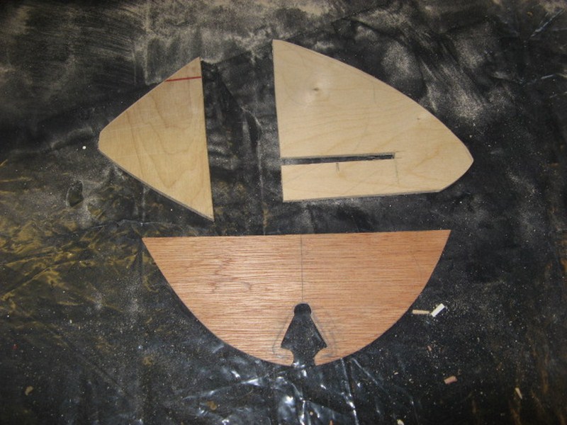   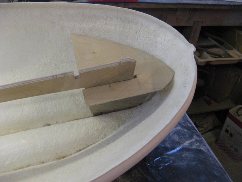 the strange cut out in the stern gusset is for the rudder stering block on the Mary Stanford only, which will allow the servo arm to pass through and operate the rudder linkage arm.
Last edited by nhp651 on Sun Jan 01, 2012 8:07 pm; edited 1 time in total |
| | | | Guest
Guest
| | Subject: Re: A lifeboat build blog...........How a kit is made! Thu Dec 22, 2011 8:13 pm | |
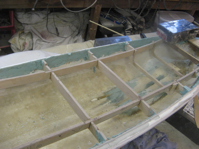
| Next, is to make the cross beams that attach to the main back bone. These are supporting the deck at vital positions and have to be measured acurately in order to co incide with the positions of the cabins. You'll see from the beams that they have a camber on them to begin with and when the notches are cut out to take the cabin supports later they (the notches) are cut parallel to the camber so that when it is all assembled finally the deck will still retain the camber from the centre to the side gunwails. They are not cut tightly to fit the beam of the boat as they need to be taken in and out of the boat several times to line things up, cut joints and generally make sure things fit, but all have to be centred up together to make sure that the next set of cuts are parallel to the centre line of the boat. These cuts are to take the next two sets of longitudinal beams that give side support to the cabins and the deck. The longitudinal beams are exact copies of the main back bone, except for the gusseted areas at bow and stern and are cut to length once the cross cuts for the cross beams are marked up exactly to give a perfect square ladder frame that will eventually support the cabin base and the decks.    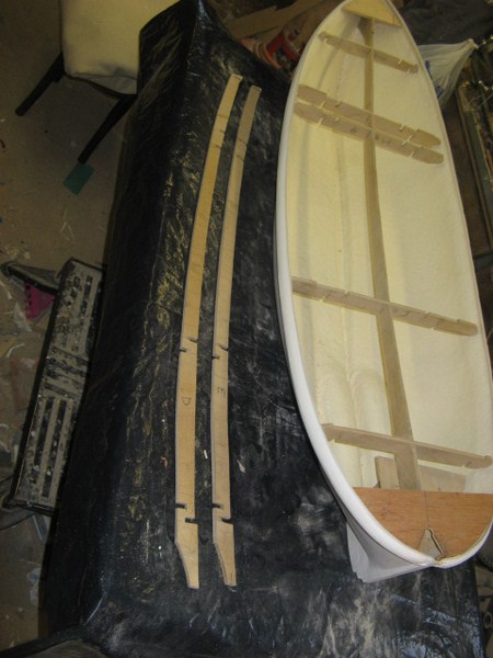 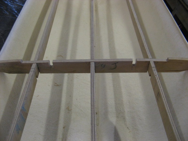  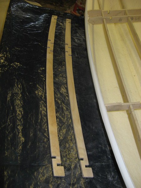 . |
| | | | Guest
Guest
| | Subject: Re: A lifeboat build blog...........How a kit is made! Thu Dec 22, 2011 8:18 pm | |
| The final cross beams are then made to support the rear larger well deck of the rear cabin, before a piece of 3mm ply is cut roughly as a base for the cabin. this will eventually sit into all the beams and so they ( the beams ) will have to be recessed down by 3mm to allow the base to fit in and fit flush to the original deck level of the beams. ONLY when all this cutting, recessing and jointing is done, and all the structure has been dry fitted with spring clamps both inside and out of the boat will it be ready for fitting, but ven then it is not glued and fitted into the boat. Other parts have to be designed first before some construction takes place. 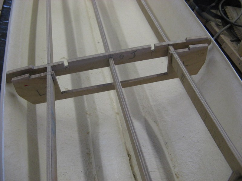    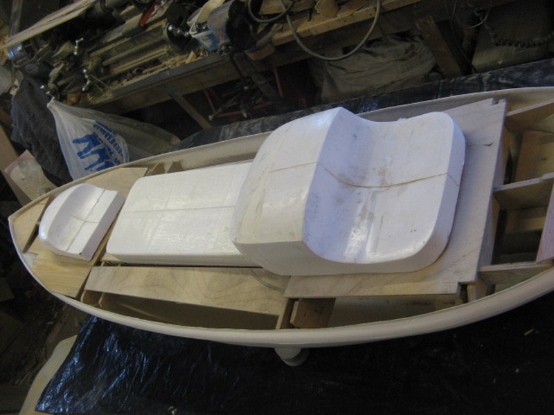 . |
| | | | Guest
Guest
| | Subject: Re: A lifeboat build blog...........How a kit is made! Thu Dec 22, 2011 8:30 pm | |
| The final part of this long process is ( once they are all cut and shaped to the shape needed ) to alphabetically mark these pieces in order of their constructional priority and then they are all taken apart again and drawn around on draughting sheet, firstly in pencil and then drawing ink. They are drawn on this draughting sheet in their own seperate thicknesses, so that once all pieces of the same thickness can be then made into a screen print to be printed into parts for the "box".
All the parts for construction. be they hatch covers, seats inside the cabin, navigation light boxes.........will all be given this treatment and all, once made into the relative knock down parts, be transcribed onto sheets pf paper in order to make a screen print off, and all with their own seperate sheets for material and thickness.....it's all fun. |
| | | | AlanP
Master


Posts : 278
Join date : 2011-06-11
Age : 80
Location : South Cumbria
| | Subject: Re: A lifeboat build blog...........How a kit is made! Thu Dec 22, 2011 10:20 pm | |
| Brilliant Neil, awaiting tomorrows installment  Alan | |
| | | | Guest
Guest
| | Subject: Re: A lifeboat build blog...........How a kit is made! Thu Dec 22, 2011 10:27 pm | |
| it'll only be a little one, as I've been banned from the workshop on christmas eve, day and boxing day, and also newyears eve and day..by the three women in my life...my wife and two daughters, lol........so will have to take some shots tomorrow, lol |
| | | | Footski
Master

Posts : 548
Join date : 2011-06-11
Age : 66
Location : Malaga, Spain
| | Subject: Re: A lifeboat build blog...........How a kit is made! Fri Dec 23, 2011 8:23 am | |
| I have never built a lifeboat before, but I am beginning to get that itch that simply will not go away....This could cost me money!!!!  | |
| | | | Guest
Guest
| | Subject: Re: A lifeboat build blog...........How a kit is made! Fri Dec 23, 2011 9:52 am | |
| lovely models they make too....you'd enjoy one barry.
neil |
| | | | Guest
Guest
| | Subject: Re: A lifeboat build blog...........How a kit is made! Fri Dec 23, 2011 3:48 pm | |
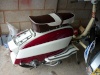
| The frames for both H F Bailey and Field Marshal and Mrs Smuts have now also been constructed and all items transfered to draughting paper ready for screen printing. the models can be seen below with both framework in place and the cabins and their bases in place, but not glued. there are slight subtle diferences between the two.   It's now time to put the frames aside and start working on the running gear which is supplied with the kit. |
| | | | Footski
Master
Posts : 548
Join date : 2011-06-11
Age : 66
Location : Malaga, Spain
| | Subject: Re: A lifeboat build blog...........How a kit is made! Fri Dec 23, 2011 8:19 pm | |
| | |
| | | | Guest
Guest
| | Subject: Re: A lifeboat build blog...........How a kit is made! Fri Dec 23, 2011 8:25 pm | |
| christmas day.....when I'm playing with my new toy helicopter and model lifeboat my daughter has made for me...we're going to pull off some stylish rescues, lol |
| | | | Guest
Guest
| | Subject: Re: A lifeboat build blog...........How a kit is made! Fri Dec 23, 2011 10:28 pm | |
| This is going to be my last set of postings until after Christmas as I've been banned from going in the workshop tomorrow, Christmas day and Boxing day, so won't be able to find my moulds, masters or fittings that I have done over the past 4 - 5 years until 27th December. All the work that I have shown you so far has been done in stages over the past few years, because other work has come along that I have had to do for others, including a lot of charity work. As you can see it's not all plain sailing and hands on 8 hours a day, and it is the same with most of those who are one man bands. Developement of new models takes second place to moulding, casting packaging of fittings , timbers, plastics..taking moulds to the moulders for new mouldings for customers, and a hundred and one other jobs that come first before the new development of forthcoming models, and as such with constant interuptions, the flow of work suffers, and a certain percentage of the time spent in the workshop on a new developement is in the thinking stage of what you were going to do next on your new model.............and then just as you are going to get on with the next part, the next piece of turning to produce that new fitting......someone will ring up with good news.....they want a new kit off you........or someine will ring up telling you your kit is a load of C*** because they haven't followed the instructions and the part won't fit correctly because they have cut it wrongly.............so you have to sort that one out as well, and the thread is again lost......... It is no bed of roses, and not fun half the time, but the rewards of seeing people who have made a lovely job of one of your kits, sometimes just makes up for it, and that is probably why manufacturers keep on doing it......all they ask for is a little understanding and good will, without the jibes that they get. So picking up the thread that I left before. I have now put the deck support frames to one side to now concentrate on the running gear. Most classes of the old double ender motor lifeboats had different rudder set ups to each other class and so most models that are being developed have to have a different set of "fittings" to make them work, and my three models are no exception. The Mary Stanford has a rudder attatched to an external rudder bar on the stern post, and the two Watson's although similar have different skegs to protect them and are set into the "deadwood" of the rear keel, and as such these skegs have to be built up from a sturdy material once the hulls have been moulded. Leaveing the mary Stanford till last, I'll deal with the two Watson's first. First job is to take a template in card of the recess that has been taken out of the rear of the hull ( and as both hulls are exactly the same) the one template will do. You can see the area vaguely that has been cut out in the first photo. Once the template has been drawn out on card, but not cut, and the piece doubled up to two templates it can be placed against the plans of the two boats, and the rudder skegs can be drawn onto the card so that it will sit in place into the apperture made when moulding the hull and then transposed onto a singe piece (each) of 6mm birch faced ply. Also whilst drawing these skegs out, the shapes of the two rudders ( as, on the two different boats, they are both different ) can be traced onto paper and then transposed onto two different thicknesses of ply wood. The rudders are made of three layers of wood for the kit maker which will give then a rudder that once made will not twist on it's own rudder bar once it gets older or knocked from time to time, in a way shown. The centre core is made from 3mm ply, the same thickness as the diameter of the rudder bar, withan outer skin on both sides of 1.8 mm ply. The rudder bar is set into a channel cut into the centre core with a right angled bend so that it cannot possibly twist once all glued together. The other pictures show the different rudder skegs and rudders, cut out in ply and not yet glued together with water resistant aliphatic resin. The skeg with the two outer skins is from the Field Marshal and Mrs Smuts, and requered this to give the effect of a trailing edge for the skeg to which securing lines could be passed through hols in the skeg when hauling back up the slip......these are not the "Ruffle" holes, which will be put into the skegs later, but just securing areas for rope ties All of these pieces are then transfered onto the relevent draughting sheets associated with each particular boat and particular sheet of the same timber thickness to be used for screen printing, after they are dry fit to see that they actually do fit. Finally the rudder for the mary Stanford can be made. This is actually a straight forward transfer of a tracing of the rudder from the plans to 4mm birch faced ply, but the fitting is totally different with no less that ten white metal and resin fittings (some of these can be seen in the last photo) being used to make the assembly work......and these fittings all have to be made from masters first, and then set into moulds, and cast before you end up with a product that will make the whole assembly operational, but that's another story. And that is where I stop until after Christmas........that process will be discussed once I can find my moulds for the stuff shown here and made some time ago.  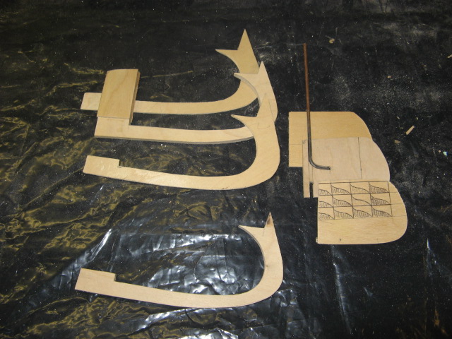  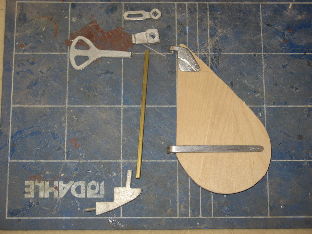 . |
| | | | Footski
Master
Posts : 548
Join date : 2011-06-11
Age : 66
Location : Malaga, Spain
| | Subject: Re: A lifeboat build blog...........How a kit is made! Sat Dec 24, 2011 8:27 am | |
| | |
| | | | Guest
Guest
| | Subject: Re: A lifeboat build blog...........How a kit is made! Sat Dec 24, 2011 12:46 pm | |
| thanks Barry,
and a merry christmas to you too...all the best, and not to much sangria......makes me thirsty thinking about it, lol |
| | | | Guest
Guest
| | Subject: Re: A lifeboat build blog...........How a kit is made! Wed Dec 28, 2011 10:57 pm | |
| The whole process from start to final dry fitting of those frame works can take anything from 3 to 15 hours depending on how complicated the construction is, and also not forgetting that some of the beams and timbers may be cut wrongly or not fitting when put together and so new pieces have to be made. It's not a case of at this or any stage that "Oh I'll correct it at the build stage"..by then it is too late as the pieces which have been screen printed will be ready for production run, and will be wrong. So now it's onto the process of making the parts that go to build the kit....the white metal and resin fittings, and without them there wouldn't be a kit. and just a note before a salutary thought to put to you.........each one of the ten + white metal and resin fittings that can be seen in the last posting picture above, took on average 1 - 2 hours to make, as the master for a mould..........and all were made in plasticard, not brass. If I had made them in brass, it would have probably taken twice the time to make each fitting. But why do I make them in plasticard, myself............. reasons.....1) as stated it probably takes half the time, and 2) I can use plasticard masters with the technique of mouldning that I use...........but here's the real reason for all those who curse the cost of a kit. The "big boys" in kit manufacturing use a different technique for making their moulds for centifugal casting.....on an industrial scale. Whereas I can use RTV ( room temperature vulcanising) rubber for my moulds which will give me limited numbers of castings before they wear out, and because they are room temperature vulcanising ( setting and hardening) and as such I can put plastics that are succeptable to heat and high temperatures and therefore would melt and distort if put through a high heat process, the kit manufacturers such as Metcalf Mouldings and Model Slipway use a much harder and firmer rubber to make their moulds for industrial usage, and multi castings with hot (250 - 300 degree) liquid white metal. This needs a rubber that will withstand such temperatures time and time again. And the only way is for them to use vulcanised rubber to make their moulds. Where as I can place my masters into plastecine and mould one half at a time ( see my pics), those using vulcanised circular rubber blanks have to make their moulds in one shot. And to do this they need a special machine.....a vulcanising machine at my last research was anything from £1500 for a well used second hand one to about £4 k for a new one. This works on heat transferance through the hard solid rubber which is placed under a press with two parts, top and bottom, and the masters are placed inbetween these two blanks, along with a number of locating studs. The machine is thermocontrolled to a temperature set, and once the temp inside the rubber is achieved, the press is wound down, thus imprinting the master into the two halves of the rubber, and then it's all left to cool. That is now why all the masters for such a process have to be made in brass and therefore much longer to make the masters. I haven't counted the masters on any of the three boats I am building, but quite a few are generic with the other two boats that I have done and so will not need to be re made for a new boat. However, the single master count ( not the actual number of white metal fittings in the kit) for the Anne Lettitia Russell is 182 seperate masters that had to be made. If each took an average of 1.5 hours ( and that is a very conservative cost of time) that is still 273 hours of solid time spent on developing the masters alone. Then you have to "cut the rubbers"....make groves into them for the molten metal to run to the imprints of the masters before you can start casting. Finally you have to work out how many of a certain fitting is needed for that boat/model and run a series of casts with the master mould to build up a set for a production mould. Say a set of stanchion is needed, at say 24 stanchions per boat..then you have to run that master mould at least 24 times to get out that number of single stanchions for a mould and then, after cleaning them all up, put them into a new set of moulding blanks, set the vulcvaniser to heat, and mould a set of moulds with 24 stanchions in them, not forgetting that you have to cut the moulds after cooling, yet again in order to take the white metal. Oh but I forget..........where do you do the casting................well a centrifugal caster of course, but not a little piddly thing like mine.......No, one that has counter ballance weights and the full jobbie........an indistial scale machine and the last time I enquired about one of those, it was going to cost me, either second hand for yet again a well worn one, to the latest in machines that could take upto 12 inch moulds............errrhhh, between £3000 - £6500....and I'm now talkiing 20 years ago. And that, my friends is just the start of it all for the "Big boys"..........so in just two moulding machines, not counting the cost of the rubber blanks which although initial outlay!!! next time I'll take a look at making a few masters myself. But just to start off with, the picture below shows a finished mould with a set of fittings which make up into the hand windless on the RNLB Mary Stanford...the masters for this took 42 hours to make from start to finish. All time, and it's amazing where time goes when you don't have to think about it. 
Last edited by nhp651 on Thu Dec 29, 2011 8:50 am; edited 2 times in total |
| | | | Footski
Master
Posts : 548
Join date : 2011-06-11
Age : 66
Location : Malaga, Spain
| | Subject: Re: A lifeboat build blog...........How a kit is made! Thu Dec 29, 2011 8:34 am | |
| When all is considered there is more work goes into producing the kit than there ever is in building one. Simply amazing.. | |
| | | | intrepid75
Master
Posts : 271
Join date : 2011-06-11
Age : 68
Location : Bristol, West country
| | Subject: Re: A lifeboat build blog...........How a kit is made! Thu Dec 29, 2011 10:54 pm | |
| COntinues to be fascinating to say the least. But Neil, do you actually ever sleep or eat? | |
| | | | Guest
Guest
| | Subject: Re: A lifeboat build blog...........How a kit is made! Thu Dec 29, 2011 11:03 pm | |
| I fall asleep at the bench,..wake up to the smell of grp resin.............. I have seriously, worked on a number of occasions over the years, during the summer months, not noticed the time when have been trying to meet a deadline, and the next thing I've noticed, the dawn has broken and the birds are singing their chorus..........quite pleasant really...and at least the good lady knows where I am.......not out on the catch, lol..........well I wasn't when I used to do that, in my younger days.......now too bl***** old to do either,  |
| | | | Guest
Guest
| | Subject: Re: A lifeboat build blog...........How a kit is made! Sun Jan 01, 2012 1:43 pm | |
| Well, I suppose I've whinged on enough about how much effort and preparation plus the big expense it takes to get a model kit off the drawing board and into production to put off all of the most hardenned nutters in the game that there are only three more jobs to do before the kit can be marketed.One is to write the set of instructions, and this is written ( i myself do it in long hand with all measurements taken and step by step process AS I ACTUALLY BUILD IT) and then convert onto the computor with spell check ON, and draw all the diagrammes for construction (free hand at first and then convert onto A3 drawings to begin with.finally reducing size on a photocopier to fit 4 or more to an A4 size sheet, draw the full size working drawings with all fittings corrulated to the list of parts on the instructions page, and finally build the prototype model from all the sums of the parts.
the build time of the model itself is probably a little longer than the average builder will build the kit...say about 600 hours.making sure that all parts fit, another 50 hours to write the instructions, convert them onto the computer( that includes the sectional working drawings of all the parts and another 20 - 30 hours to do draghts of the plans and then final working drawings.
And there you have it.....I haven't totted up the total amount of hours spent on developing a kit, nor what you would be charged if a "professional" on "professional wages" such as mechanic at your local garage would charge.................I don't want to frighten myself, never mind others who would want to start up in the "game"............I'll let you do that, lol.
But I'll now get down to just building the three prototypes.
As all of the models I have built in the past ( and I do not count the Rother class lifeboat that Dave Metcalf produces, as I had no input into that model what so ever but it is included in this next statement)......... they are all of what we call the "Classic double ender" lifeboat era, from the mid 1920's up until the final Rother was produced in 1982 and all used certain generic parts to their builds, and as such certain fittings from one model can be used on another boat with reasonable scale correctness.
Although certain minor differences might occur they are not too great that (say for instance) the stanchions on the Rother can be used for the Barnett, and the "A" frames for the tail shafts on the Rother can be used for the Watson class 46' boats, and also used with these brackets, the feet from the little Liverpool class boat can also be used for the Watson on the ends of the Rother A frames.
It makes life a little easier and for all but the very purist in lifeboats( and that is why I try to stick with the classics rather the modern fast afloat boats) if brings the old classic lifeboat into the relms of the model builder who would normally be put off by trying to manufacture those difficult parts like the beltiing and propeller tunnels.
Also as more of these classics are developed, the more the range of fittings are available to build into them, and to be honest, with the final sets that are to go on these three boats, there will be very few fittings now left that aren't available to build the type of boat you desire. |
| | | | Guest
Guest
| | Subject: Re: A lifeboat build blog...........How a kit is made! Sun Jan 01, 2012 1:44 pm | |
| So, finally to the build. First job will be to clean all the moulding marks from the belting and the keel and stem/stern posts ( of which I have omitted to do on the prototypes at the moment. Next is to fit the running gear of prop shafts,A frames and then rudders. I found that I only had one set of brackets for the Watson, and had had to in the past, make up a new set ( as there were no generic ones to fit ) for the Barnett, Mary Stanford....and so I'll just run through the steps to make a set of brackets first. these would also be normally cast in white metal after moulding. Take a round of brass to make the bearing that will be inserted into the boss of the A bracket, and using a laithe, drill the centre with the diameter of the propeller shaft, ( in this case 4mm) and then shape the bearing in the laithe, putting on a flange at one end, and the outer diameter to ( in this instance) 6mm. set aside. Take a round of brass for the hub of the bracket boss, and centre drill for the hole to take the bearing, which will be a 6mm hole to take the 6mm outside diameter of the bearing. The bearing will then eventually slide into the boss. Shape the boss in the laithe to that shown on the set of plans, use carburundum tape to clean up, and then using a parting tool, cut off the boss from the brass round. Repeat this process for the second boss for it's twin A frame. Take some length of flat bar ( or if needed shape the bar with a file,/grinder/sander if you want to get the profile of the legs exactly as per boat....but that's for the purist) and jigging up, silver solder the legs to the boss at the correct angle required on the plans. cut the legs to fractionally over length, and set aside for a few minutes. Take a length of nylon rod about 10mm longer than the length of the boss......this is to go through the boss of the A frame which will go into the rubber mould with the A frame assembled. Make a rubber mould from two layers of RTV rubber as in the pictures, using lego boxes and plastecine for the process of moulding. The box is made and a layer of plastecine is put into the box...............the part to be moulded is pressed into the plastecine half way ( this is the process, using RTV rubber for any fitting part) and the round of nylon is moulded in the rubber.Also small impressions are made into the plastecine for locating pins to form in the rubber, in order to stop the mould from sliding later when moulding, ( thus giving an overlapped mould, which would be useless) Rubber is poured into the exposed half of the fitting and alowed to set, usually overnight. Once set, the plastecine is removed to expose the unmoulded half and the exposed rubber of the first half is sprayed with a release agent, so thet the two halves of the mould won't stick together. Pour into the seconf half the RTV rubber again to finally cover the master that you have made. Once cured, remove the rubber from around the master revealing a berfect female mould of your master. Cut track ways for the metal to flow in, airways for the trapped air to escape, take the nylon out of the master and put back into the rubber mould, put the mould between a sandwich of two pieces of 4- 6 mm ply , hold together with clamps and pour into the access hole your white metal......allow to cool and then remove the moulding from the mould.............remove the nylon rod from the mouylding....and Hey presto...you have an A frame with a hole running through it for the bearing. The process is shown below for making an A frame in pictures. the brazing hearth is a constitute material called Vermiculite and obtained from such a place as this... http://www.ebay.co.uk/itm/Soldering-Mat-Pad-Brick-Board-Brazing-Hearth-/120799566544?_trksid=p3284.m263&_trkparms=algo%3DSIC%26its%3DI%26itu%3DUCI%252BIA%252BUA%252BFICS%252BUFI%26otn%3D21%26pmod%3D260898624510%26ps%3D54 and is very cheep for what it is..can be cut with a saw, made into any shape and is just superb for brazing. 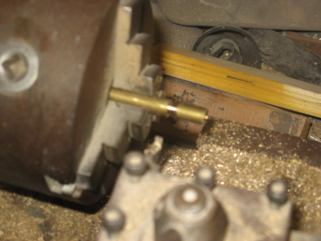       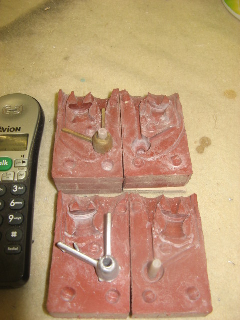 |
| | | | Guest
Guest
| | Subject: Re: A lifeboat build blog...........How a kit is made! Sun Jan 01, 2012 3:23 pm | |
| |
| | | | Footski
Master
Posts : 548
Join date : 2011-06-11
Age : 66
Location : Malaga, Spain
| | Subject: Re: A lifeboat build blog...........How a kit is made! Mon Jan 02, 2012 7:50 am | |
| Fascinating. I like the moulding method...Very effective. How many uses would you get from an 'A' frame moulding Neil? | |
| | | | Guest
Guest
| | Subject: Re: A lifeboat build blog...........How a kit is made! Mon Jan 02, 2012 11:09 am | |
| i've cast 20 white metal ones from that rubber at the moment without any deterioration to the rubber, barry, and just between christmas cast 22 mouldings from some lighter rubber and with white metal still no deterioration |
| | | | Guest
Guest
| | Subject: Re: A lifeboat build blog...........How a kit is made! Tue Jan 03, 2012 6:58 pm | |
| Today was spent constructing the two different rudder skegs for the Watson lifeboats. They were both made from a core of 6mm birch faced ply sandwiched between two layers of 1.8mm birch faced ply, and glued together with a waterproof glue. they are also seen with the rudders in place which also were made in the same way of sandwiched timber. The skegs were drilled with a 4.5mm drill bit to take a sheath of plastic tube which will be the housing in the skeg for the lower rudder rod, and also which will be set into a block of timber inside the boat to support another length of plastic tubing for the upper rudder rod. 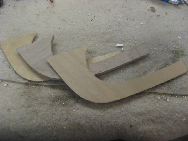 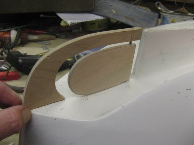   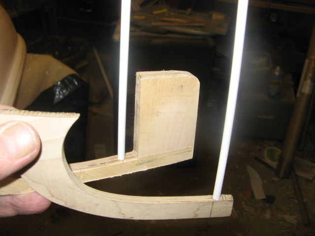 . |
| | | | Guest
Guest
| | Subject: Re: A lifeboat build blog...........How a kit is made! Wed Jan 04, 2012 9:25 pm | |
| The skegs have been dry fitted now, the plastic inserts put into the skegs and blocks to take the rudder tubes have been drilled, inserts placed in and rudder bars cut to length ready for tomorrow when I'll pin them from both inside and outside with 2mm brass pins to both locate and keep them straight and true whilst gluing with 2 part liquid epoxy. The Hulls have also been sanded to get rid of all moulding lines and levelled the bulwark tops off. The support block for the rudder tube is made from obeche and a piece of the same , size included, along with a length of plastic tubing has also been set aside ready to go into a parts bag for each boat, for later collation when putting the part for the kits together. the obeche block will be set onto the hull of the boat using polyester body filler to give a firm watertight grip between block and hull.  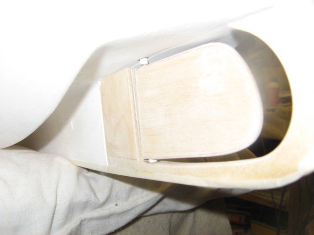  . |
| | | | Guest
Guest
| | Subject: Re: A lifeboat build blog...........How a kit is made! Thu Jan 05, 2012 6:33 pm | |
| Some say that scratch building hones the little grey cells to think laterally, others say it's the mother of all inventions. Even more so when you are also trying to make it an easy build for others to copy. Well, I hit a problem.......or perhaps a quandry this afternoon when trying to fit the skegs, with all locating pins in position and the rudder in possition as well................it just wouldn't fit. But the pins are needed to hold firm and make sure that if the skeg gets knocked when sailing, it wouldn't part company with the grp hull. So I thought a while and then decided that the two pins that were causing the problem and not allowing the skeg to "drop" into possition were the two horrizontal pins on each boat that fit into the vertical face of the end of the grp keel. If I could overcome this problem but keep those pins, all would be fine. A bit more thinking and looking at the holes already drilled and I thought that if these drill holes became a slot in the end of the keel for the pins to fall into, the problem would be solved, as the slot could then, on glueing the skeg in place, be filled with 2 part epoxy whilst gluing the rest of each skeg in possition. So, having already drilled the holes, I re inserted the drill bit into the top hole, and then keeping the drill spinning turned the drill bit upwards to ream out the hole into a slot.Likewise I did the same with the bottom hole and joined that up with the top hole which has already become the slot. Now, with one downward motion, the skeg, and rudder can be pushed into possition and glued up, and held in place with tape and clamps until set. However the wooden parts are now off to the "paint bay" to be given several coats of sanding sealer and rubbed down with wire wool ready for when the boat is sprayed up later. The photos show firstly the marking up and then the pins set into the skeg, plus the slot.  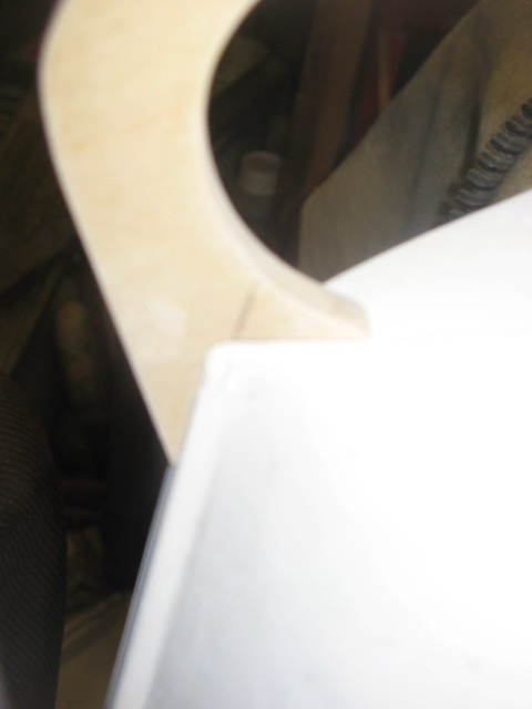 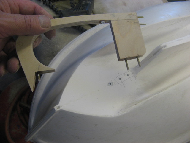 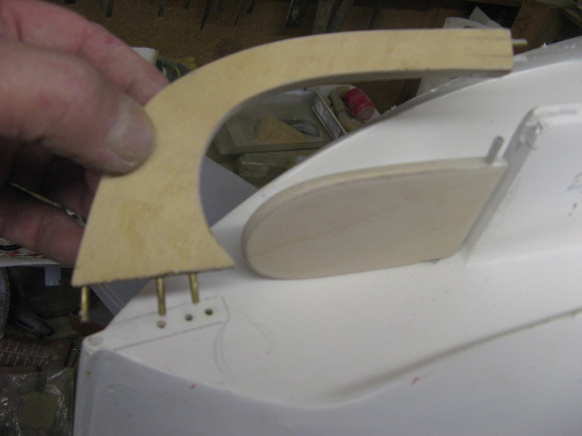 . |
| | | | Footski
Master
Posts : 548
Join date : 2011-06-11
Age : 66
Location : Malaga, Spain
| | | | | Guest
Guest
| | Subject: Re: A lifeboat build blog...........How a kit is made! Fri Jan 06, 2012 12:05 pm | |
| cheers, Barry. the rudder skegs have now all been located, and glued in place. Even though the rudder bar is running in plastic tubing to aid smooth movement, I have still injected into the plastic guide tubes a mixture of vaseline/carbon powder to aid lubrication and barrier against water ingress. The skegs were all glued with 2 part epoxy. I have also written into the instructions the alternative method of fixing the lower leading edge of the wooden skegs on H F Bailey and Field Marshall and Mrs Smuts with a biscuit of 1.8 mm ply as suggested by our ozzie friend RaaArtygunner..........Pondered it last night for some time and on how to cut the slot rather than drilling out and agreed that it was a good idea. The method of cutting I thought of instead of drilling out would be to use a saw and cut in to the wooden skeg and the keel leaving a triangular section in each, into which a right angled triangular piece of ply could be glued and fitted. Thanks for the idea, RR The only reason I didn't use it on these two models is that I'd already stuck the pins into the wooden skeg with epoxy before the suggestion and didn't want to damage the skeg by trying to remove them in favour of a sawn slot, which will accomodate a triangular biscuit. As I said earlier, certain fittings can be used on similar boats, and the white metal skeg used on the earlier designed Anne Letitia Russell, can be used on the Mary Stanford, as I have done. However it is a little thinner than the M.S.'s keel and so sandwiches of 1.8 mm ply on both sides of the white metal rudder skeg have been cut, drawn onto the screen prints and then glued into place using 2 part epoxy and clamped. The pictures below show, mary Stanford, field Marshall and Mrs Smuts and H F Bailey, respectively. I shall now wait for it all to set, and then clean of exess epoxy, and fill all parts with filler....reminds me, I've run out......off to the car factors for some more..better a big tin this time.lol 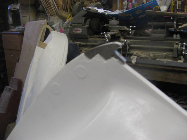    . |
| | | | Guest
Guest
| | Subject: Re: A lifeboat build blog...........How a kit is made! Fri Jan 06, 2012 12:23 pm | |
| |
| | | | Guest
Guest
| | Subject: Re: A lifeboat build blog...........How a kit is made! Fri Jan 06, 2012 12:26 pm | |
| cheers damien.
how did your op go the other day.....extremely well i hope.
neil. |
| | | | Guest
Guest
| | Subject: Re: A lifeboat build blog...........How a kit is made! Fri Jan 06, 2012 12:45 pm | |
| Hi Neil, the ultrasound found a 9mm gall stone and a mass they called black sludge guess I'm over due for an oil change.
I've been referred to the relevant Surgeon and put on waiting list for gall bladder removal if your public health is like ours you'll know it's a waiting game could be soon could be 12 months or more. Just have to put up with it and take pain killers when pain gets BAD.
Such is life.
Thanks for asking m8.
|
| | | | Guest
Guest
| | Subject: Re: A lifeboat build blog...........How a kit is made! Fri Jan 06, 2012 12:49 pm | |
| Take care matey..at least you now know what it it....worst thing is not knowing and taking an age to be told.
My sister in law has just gone though the mill with breast cancer..but at least they finally found that it hasn't spread to the other vital bits, so she goes in on Monday for her opp...hope it goes well.
neil. |
| | | | Guest
Guest
| | Subject: Re: A lifeboat build blog...........How a kit is made! Fri Jan 06, 2012 12:59 pm | |
| Wish her my best wishes Neil It is the biggest shock one can get being told you have a Tumour or Cancer next is being told you'd be more comfortable at home a you wait out the next 3 week before death that was 17yrs ago I beat IT & Them tell her she needs to be VERY Positive she'll beat it, no doubts at all. That goes for all her friends and family the more positive energy around her the better her chances.
Damien, |
| | | | Guest
Guest
| | Subject: Re: A lifeboat build blog...........How a kit is made! Fri Jan 06, 2012 1:37 pm | |
| she's had a bad time over the past few years. Went rambling on the hills and fells of the english lake district some years ago, and then fell ill...came out with bruises all over her. she was diagnosed with a very aggresice form of Luekemia, and the surgeons asked her if she woerked in the Nuclear fuels/generating industry, to which she said no...he returned with the news that she could only have caught this form of Luekemia by being in close contact with radio active particles and such.
She then said that she had been walking on the fells above Sellarfield ( a nuclear fuels reprocessing plant in our lakes district)............he just raised his eyebrows and said "there's your contact".....very scary.....but she fought and won that one, and the prognosis for this is apparently very good, so will pass on your best wishes.
neil. |
| | | | Guest
Guest
| | Subject: Re: A lifeboat build blog...........How a kit is made! Sat Jan 07, 2012 9:15 pm | |
| The final part of the Mary Stanford Rudder skeg arrangement has been fitted..........the false stern post that the rudder up/downhall brackets will be attached too, but these, being vulnerable to knocks and brakage if fitted at this point will be fitted later in the build. The stern post was made from 3mm ply and glued and pinned with 2.4mm brazing rod before being filled and later sanded smooth with polyester filler.  Next will be fitting the prop shafts and "A" frames on all three boats. |
| | | | Guest
Guest
| | Subject: Re: A lifeboat build blog...........How a kit is made! Sat Jan 07, 2012 10:26 pm | |
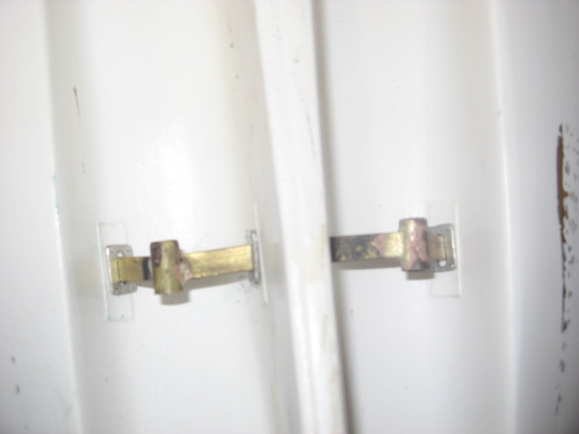
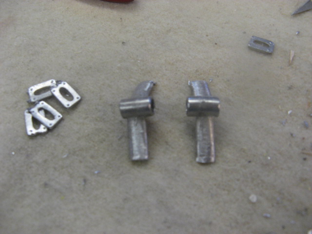
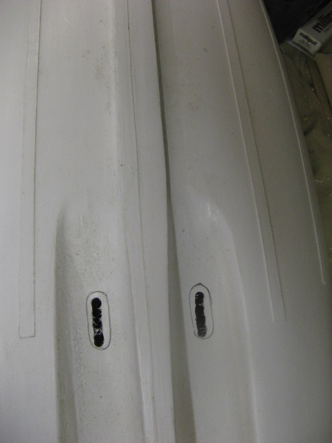
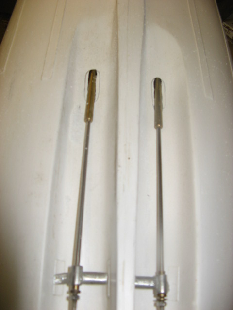
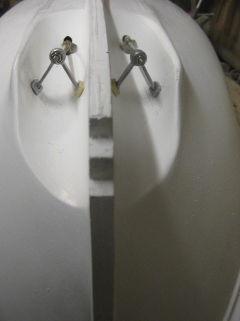
| This was the part I was dreading most, as getting these things lined up in the tunnels is probably one of the most important processes of making a classic lifeboat, and has to be close on perfect to get the maximum out of the propellers, which are limited in size anyway to the inner dimensions of the tunnel. the sizes are laid down anyway by the class of lifeboat anyway, and the prop shafts have to run true down the tunnels. To start with, I assembled the prop tube/shaft with the "a" bracket and the end locking nut for the propeller. I had already glued the bearing into the "A" bracket ready and made sure that the shaft rotated in the bearing with ease. I have also found that these assemblies have a tendency to slide around all over the place and never stay in one possition.ie, the tube will creep up the shaft and then the whole thing is out of position when glued, so I have in the past, and here, locked the prop tube onto the shaft at the desired position with masking tape.......easily removeable once the job is finished and glued up. Starting with a pilot hole in the centre of a raised piece on the moulding and enlarging to an oval allows the prop tube to sit in neatly. As the tube is locked in position to the shaft, the only thing now that is moveable on the shaft is the "A" bracket, which is put into place at the tail of the shaft, and close to the raised markings on the tunnel that correspond with the approximate position of the bracket. The bracket is rotated untill the shaft is centred in the tunnel, and the centre of the shaft is at the correct hieght above the top of the tunnel wall ( as depicted on the plans) and then the possition of where the legs meet with the tunnel wall is marked in pencil. The whole assembly is then removed and the markings of contect between legs and tunnel are covered with masking tape. Onto the legs are placed the "feet"....white metal brackets that make gluing contact with the tunnel, and also house the legs in a slot. Two part epoxy is then applied to the ends of the legs and the whole assembly is put back into position, making sure that the feet to the legs glue and set whilst touching the tunnel.....they will then be left to set for an hour, whilst working on the next boat in exactly the same way, but with different brackets and shaft lengths for the two watsons in comparrison with the Barnett........Mary Stanford. Once set, the feet are drawn around with pencil to reviele when the assembly is removed again, a square. The square marks the gluing area, and I now, using a 1.5mm drill bit drill multiple holes on the inside of this square to give a "keying area" got the adhesive to cling into. I also drill some holes into the feet and the ends of the legs of the "A" bracket for the same "key". Remove the masking tape Mixing some polyester filler I put some into the leading and trailing edge of the oval which takes the prop tube into the hull at the forward end of the tunnel and also a liberal amount ( it can always be taken off when set) onto the bottom of the feet which make contact with the tunnel wall. The assembly is put into the hull at the correct possition and the feet make upto the tunnel wall in ( by now ) the exact pre determined position. it is held in this position with masking tape until the filler sets and cures.another hour, whilst I can turn my attention to the next boat. Finally turning each boat upside down I can now fill around the entry holes where the tubes come into the hull with polyester filler. Whilst doing this, you'll see the area where the filler has squeezed through from the base of the feet......this area can be reinforced with some more filler to bond all that has been used to glue the "A" bracket into the hull. set aside to cure before taking the prop shafts out to clean up around the base of the feet with abrasive paper.      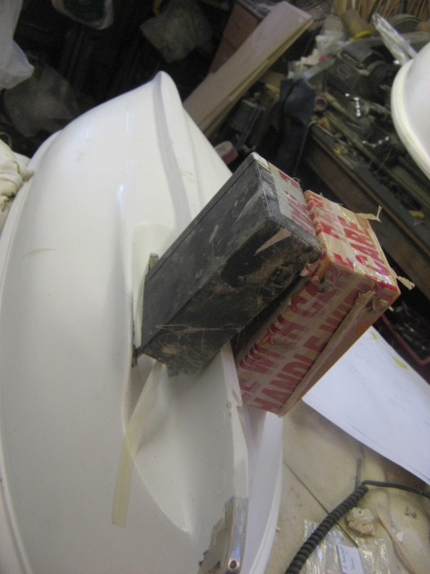  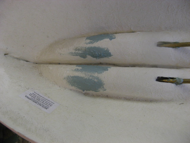 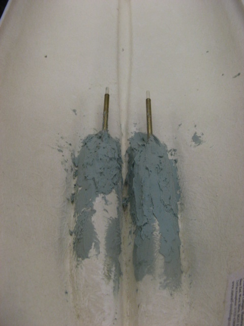  . |
| | | | Guest
Guest
| | Subject: Re: A lifeboat build blog...........How a kit is made! Sat Jan 07, 2012 10:35 pm | |
| Finally all three boats together showing the different rudder arrangements. That process only took 4.5 hours from start to finish, and although they say the camera never lies....the shots show the skegs all over the place and the prop tubes totally uneven..........was mortified when I saw the shots.....can assure you, they are all set even, straght and level..............think I'll buy a new camera, lol 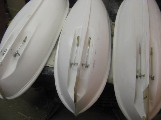 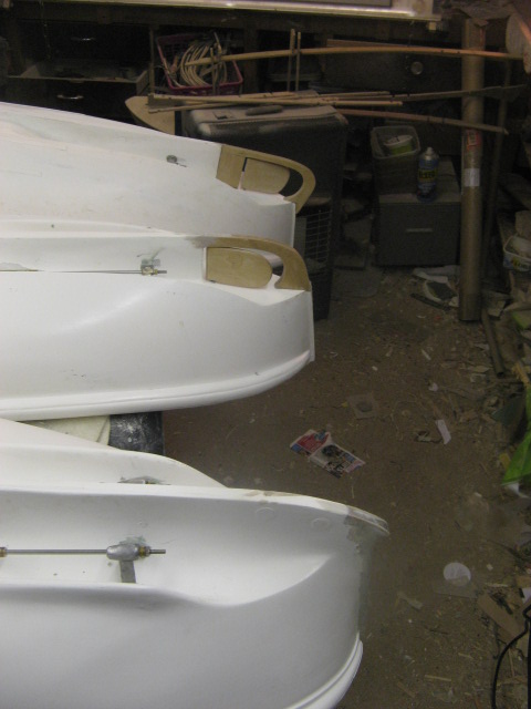  . |
| | | | phil winks
Master

Posts : 583
Join date : 2011-06-12
Age : 68
Location : Taunton
| | Subject: Re: A lifeboat build blog...........How a kit is made! Sat Jan 07, 2012 11:20 pm | |
| Hi Neil its taken my some time to catch up on this thread and well worth it too. A most interesting and informative read. well up to your usual standards mate please keep it up | |
| | | | Guest
Guest
| | Subject: Re: A lifeboat build blog...........How a kit is made! Sat Jan 07, 2012 11:41 pm | |
| cheers, Phil
........I will.
now that the prop shafts are in, it will be quicker progress as soon as the decks are on as ALL the fittings are made and ready........I'll start having fun now.......and hope to have them ready for the Leicester Lifeboat rally on my birthday in June, 3rd......well those are my plans..but you know what happens to those.
neil |
| | | | HS93
Lost But Never Forgotten R.I.P

Posts : 69
Join date : 2011-06-11
Location : merseyside
| | Subject: Re: A lifeboat build blog...........How a kit is made! Sun Jan 08, 2012 2:07 am | |
| arnt the shaft tubes supposed to touch the proppelors:P have you got to much of them on the inside ????  Peter:lol!: | |
| | | | Guest
Guest
| | Subject: Re: A lifeboat build blog...........How a kit is made! Sun Jan 08, 2012 8:54 am | |
| No, No ,No, Peter...on that one I won't budge one inch..........as a scale boat they are supposed to represent either the exposed shafts or on some boats the sleaved shafts of the old boats, and as such giving an exposed shaft on a model is far closer to scale diameter than would be to run the tube at it's diameter up to the A frame..........that's what the big argument was all about on mayhem...........and in fact the guy who I had the argument with me, finally conceded by pm to me that he had made a blunder but counldn't now rectify it without damaging his hull???
So, no, and not by many lifeboat modellers have the shafts been wrongly placed.....and on that one, I won't argue any further.
neil. |
| | | | phil winks
Master
Posts : 583
Join date : 2011-06-12
Age : 68
Location : Taunton
| | Subject: Re: A lifeboat build blog...........How a kit is made! Sun Jan 08, 2012 3:13 pm | |
| totally agree with you Neil as long as the "A" frames or motor bearings are solid enough to cope with the thrust (dependant on which is being pushed on) then this is definately the way to go | |
| | | | Guest
Guest
| | | | | Guest
Guest
| | Subject: Re: A lifeboat build blog...........How a kit is made! Wed Jan 11, 2012 12:46 pm | |
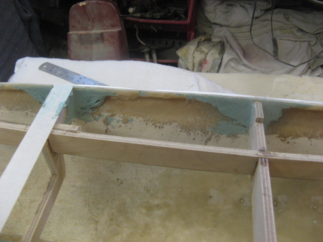
| The bilge keels and skegs have now been attached using epoxy adhesive, and the pins have been bonded in on the inside of the hull with two thin layers of polyester resin and glass matting, allowed to cure and then the pins protruding have been ground down smooth. later I'll fill any irregularities on the outside between hull and skegs with filler. 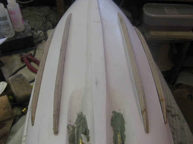 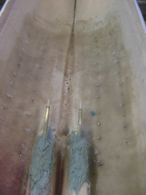 . |
| | | | Guest
Guest
| | Subject: Re: A lifeboat build blog...........How a kit is made! Wed Jan 11, 2012 12:53 pm | |
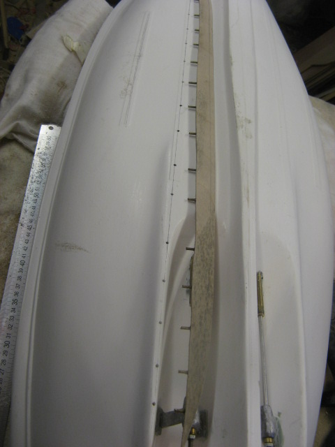
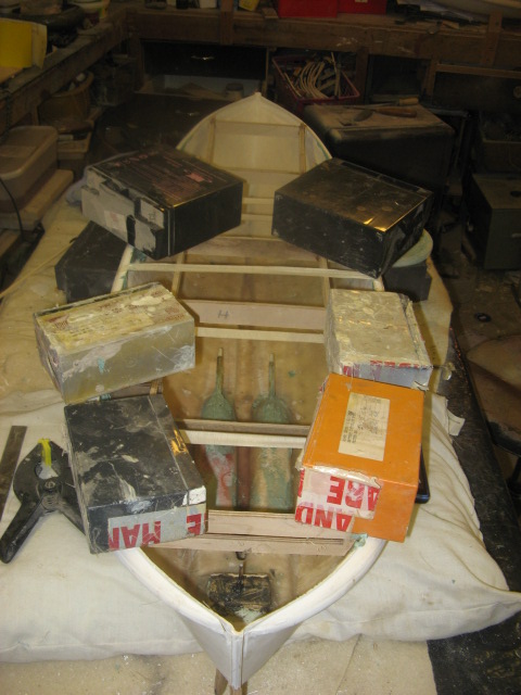
| Although I haven't yet sanded down the outside parts, and surplus filler from all parts, there is a reason.......I want to get the hulls nice and rigid before attacking them with sander and abrasive papers, and would like something to grip hold of...there's nothing worse than a big wide unwealdy slippery hull to be resting on a bench, on your knee or anywhere else you fancy and not being able to hlod it because there's nothing to get a grip of.......so the next step is to set into the hulls, the ladder frameworks for the deck supports that I glued up earlier. These are set in place with polyester filler......... Firstly I set them into the correct position with the frames in exactly the correct pre-marked place so that when the upper works are set onto the deck, they are precisely where they should be.. The hull is taped closed........hulls have a bit of a tendency to move a little, and opver the past 4 - 6 years when these were orriginally moulded, the sides of them have sagged outwards as things have been dumped on top of them in dry storage..........so I have nipped them in to the correct beam using masking tape to get them correctly beamed. Once this was done, I used filler first to tack the beams into the concave bulge made by the belting on the outside of the hull. Once they have all been tacked in, I filled in that hollowed area again with filler so that once set, I can glue to the inner edges of the bulwarks, some strips of 6 x 6mm sprue as a support for the outer edge of the deck. these will be fitted next, once the support frame has completely set inside the hull. It might look incredibly messy at the moment, but all will be fine once sanded down.  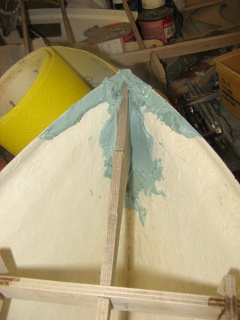 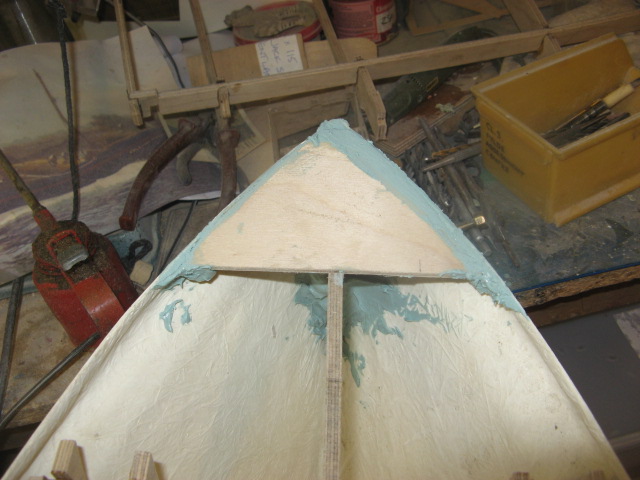     . |
| | | | Guest
Guest
| | Subject: Re: A lifeboat build blog...........How a kit is made! Wed Jan 11, 2012 3:35 pm | |
| |
| | | | Footski
Master
Posts : 548
Join date : 2011-06-11
Age : 66
Location : Malaga, Spain
| | Subject: Re: A lifeboat build blog...........How a kit is made! Wed Jan 11, 2012 5:28 pm | |
| Oh boy Neil, you will need plenty of sand paper and elbow grease!!! | |
| | | | Guest
Guest
| | Subject: Re: A lifeboat build blog...........How a kit is made! Wed Jan 11, 2012 6:29 pm | |
| oh matey.....I had a sonic sander bought me for chrimbo......going to give that a try.......should rip into all that like a hot knife through butter. |
| | | | Footski
Master
Posts : 548
Join date : 2011-06-11
Age : 66
Location : Malaga, Spain
| | Subject: Re: A lifeboat build blog...........How a kit is made! Wed Jan 11, 2012 7:41 pm | |
| Ah.....progress will be made then... | |
| | | | Guest
Guest
| | Subject: Re: A lifeboat build blog...........How a kit is made! Wed Jan 11, 2012 8:21 pm | |
| Sorry about the short reply barry.....was dragged off to make the beds..a womans work is never done....then tea, then a bath.the kids are all in bed now so have a little peace and quiet, lol
yes I was bought an american bit of kit for christmas.a sonic tool that vibrates at 20000 rpm from a company called worx.not to be confused with aldi' workbox.....and all the toold are either tungsten or diamond tipped.a real vast aray of 50 tool heads to choose from so there'll be something I can do a bit of damage with...............but apart from the under deck, the sub deck and then the printed planked decks to put on it'll start to now take shape, and look like a lifeboat or three, lol
cheers, neil. |
| | | | Sponsored content
| | Subject: Re: A lifeboat build blog...........How a kit is made! | |
| |
| | | | | | A lifeboat build blog...........How a kit is made! | |
|
Similar topics | |
|
| | Permissions in this forum: | You cannot reply to topics in this forum
| |
| |
| |